Consider the motion of a single particle P of mass m in a circular path of radius r. suppose this motion is taking place by attaching the particle P at the end of a mass-less rigid rod of length r whose other end is pivoted at the center O of the circular path, as shown in Fig. 5.1 (a). As the particle is moving on the circular path, the rod OP rotates in the plane of the circle.
The axis of rotation passes through the pivot O and is normal to the plane of rotation. Consider a system of axes as shown in fig. 5.1 (b).
The z-axis is taken along the axis of rotation with the pivot O as origin of coordinates axes x and y are taken in the plane of rotation. While OP is rotating, suppose at any instant t, its position is OP1, making angle ϴ with x-axis. At later time t + ∆t, let its position be OP2 making angle Ө + ∆Ө with x-axis (Fig. 5.1c).
 |
 |
 |
 |
Angle ∆ϴ defines the angular displacement of OP during the time interval ∆t.
For very small values of ∆Ө, the angular displacement is a vector quantity.
The angular displacement ∆ϴ is assigned a positive sign when the sense of rotation of OP is counter clock wise.
The direction associated with ∆Ө is along the axis of rotation and is given by right hand rule which states that
Grasp the axis of rotation in right hand with fingers curling in the direction of rotation; the thumb points in the direction of angular displacement, as shown in Fig 5.1 (d).
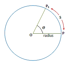
Three units are generally used to express angular displacement, namely degrees, revolution and radian. We are already familiar with the first two. As regards radian which is SL unit, consider an arc of length S of a circle of radius r (fig 5.2) which subtends an angle 0 at the centre of the circle. Its value in radians (rad) is given as


Or S = rӨ (where Ө is in radian) ……… (5.1)
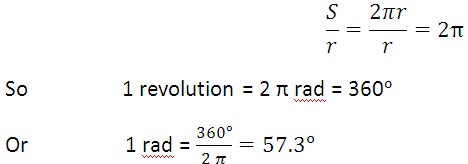
If OP is rotating, the point P covers a distance s = πr in one revolution of P. in radian it would be

Angular velocity
Very often we are interested in knowing how fast or how slow a body is rotating. It is determined by its angular velocity which is defined as the rate at which the angular displacement is changing with time. Referring to Fig. 5.1©, if ∆Ө is the angular displacement during the time interval ∆t, the average angular velocity ωav during this interval is given by
The instantaneous angular velocity ω is the limit of the ratio ∆Ө/∆t as ∆t, following instant t, approaches to zero.
In the limit when ∆t approaches zero, the angular displacement would be infinitesimally small. So it would be a vector quantity and the angular velocity as defined by Eq. 5.3 would also be a vector. Its direction is along the axis of rotation and is given by right hand rule as described earlier.
Angular velocity is measured in radians per second which is its SI unit. Sometimes it is also given in terms of revolution per minute.
Angular Acceleration
When we switch on an electric fan, we notice that its angular velocity goes on increasing. We say that it has an angular acceleration. We define angular acceleration as the rate of change of angular velocity. If ωi and ωf are the values of instantaneous velocity of a rotating body at instant ti and tf, the average angular acceleration during the interval tf – ti is given by
The instantaneous angular acceleration is the limit of the ratio as approaches zero. Therefore, instantaneous angular acceleration is given by
The angular acceleration is also a vector quantity whose magnitude is given by Eq. 5.5 and whose direction is along the axis of rotation. Angular acceleration is expressed in units of rad s-2.
Till now we have been considering the motion of a particle P on a circular path. The point P was fixed at the end of a rotating mass-less rigid rod. Now we consider the rotation of a rigid body as shown in Fig. 5.3. Imagine a point P on the rigid body. Line OP is the perpendicular dropped from P on the axis of rotation. It is usually referred as reference line.
As the body rotates, line OP also rotates with it with the same angular velocity and angular acceleration. Thus the rotation of a rigid body can be described by the rotation of the reference line OP and all the terms that we defined with the help of rotating line OP are also valid for the rotational motion of a rigid body. In future while dealing with rotation of rigid body, we will replace it by its reference line OP.


