This Free video tutorial will explain how to model a gear with polygon. After this tutorial you will be able to model gear system for your machines.
Text tutorials of “Modeling 3D Gear in Maya” ……..
Escalator is commonly used in five star hotels, commercial markets, banks, city complexes etc. Of course this tutorial is of Mechanical field. You are not going to cover each and every mechanical object of an escalator in this tutorial. You’ll simply try to understand the Mechanism; you will roughly animate some gears, you will learn techniques, active rigid bodies, a little physics, and much more.
How an escalator runs?
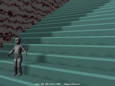
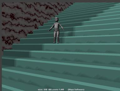
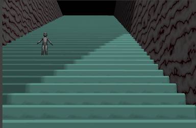
There is a system of gears, beyond an escalator’s mechanism. Electric Motor runs gears, wide leather belts bear the burdens, and staircase railings control the motion and friction of an escalator. In the image below you don’t find the actual gearing system, but you will understand the logic of mechanisms and physics of power.
Actually the logic behind a Machine is very simple.
Normally it is said that you may increase the Power of one gear by interlocking it with the other and it is also said that size and number of gears is the main thing which creates all mechanical motions.
Modeling an escalator is a special task, common staircase 3d Model doesn’t work properly. So you will have to model a rough object for the experiment of machine. Therefore this tutorial contains some details of necessary modeling of such things.
Let’s start our mechanical Modeling and Animation Project.
- Create a poly cylinder from create menu
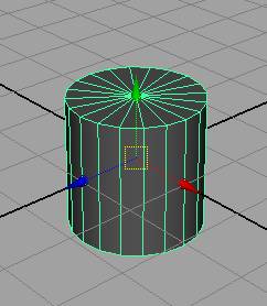
- Change scale Y to 0.138
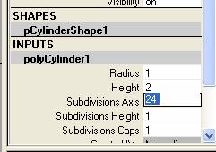
- Change Subdivision Axis to 24 from channel box
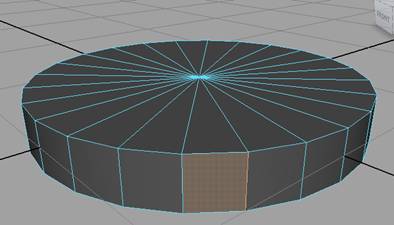
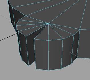
- Right click on the object and select face
- Select one of the face from height of the cylinder
- Again right click and select edge
- Select one edge of the selected face, see image below
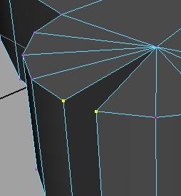
- Go to Edit Mesh Menu and select wedge face
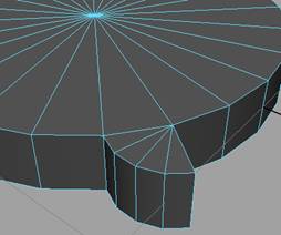
- Select very next face to the wedged face and change the direction of wedge face, see the image below
- Right click on object and select vertex
- Select two corner vertices of the wedged face
- Go to Edit Mesh Menu and merge vertices with default settings
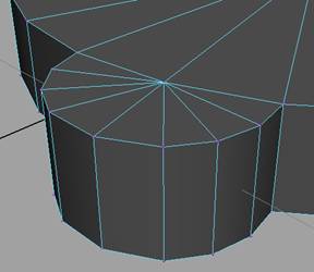
- Select all faces one by one and do the same things
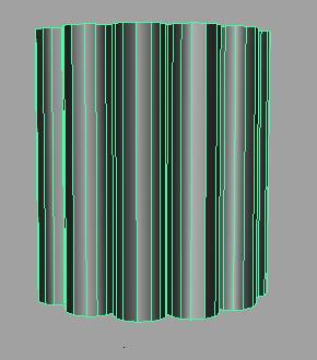
- Repeat the procedure again and again until you get the following result
- Scale the object on Y Axis 10 units
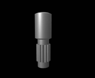
- Insert another cylinder in it or select top and bottom cap faces and then extrude them, choose your own ease
- Select upper faces and stretch them out with extrusion command
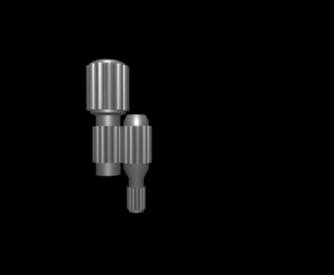
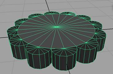
- Ultimately make shape like following one,
- Make the gears of your desired number
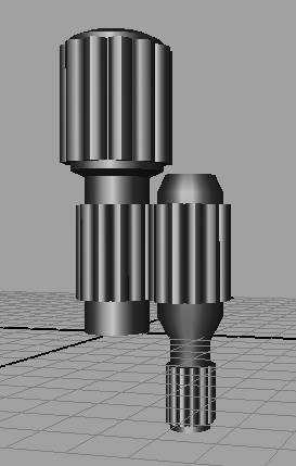
You can use other methods but you must have some gear object before assigning active rigid bodies from soft/rigid bodies menu